Watch, Like, and Share on Facebook
Digital Signal - Low and High State 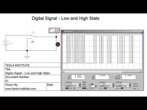
Welcome to TESLA INSTITUTE Facebook Page


Digital Signal - Low and High State
Welcome to TESLA INSTITUTE Facebook Page

A programmable logic controller, as illustrated beow, consists of two basic sections:
• the central processing unit
• the input/output interface system

Programmable controller block diagram
The central processing unit (CPU) governs all PLC activities. The following three components, shown in below, form the CPU:
• the processor
• the memory system
• the system power supply

Block diagram of major CPU components
The
operation of a programmable logic controller is relatively simple. The
input/output (I/O) system is physically connected to the field devices
that are encountered in the machine or that are used in the control of a
process. These field devices may be discrete or analog input/output
devices, such as limit switches, pressure transducers, push buttons,
motor starters, solenoids, etc. The I/O interfaces provide the
connection between the CPU and the information providers (inputs) and
controllable devices (outputs).
During its operation, the CPU completes three processes: (1) it reads, or accepts, the input data from the field devices via the input interfaces, (2) it executes, or performs, the control program stored in the memory system, and (3) it writes, or updates, the output devices via the output interfaces. This process of sequentially reading the inputs, executing the program in memory, and updating the outputs is known as scanning. Figure below illustrates a graphic representation of a scan.

Illustration of a scan
The
input/output system forms the interface by which field devices are
connected to the controller (see Figure below). The main purpose of the
interface is to condition the various signals received from or sent to
external field devices. Incoming signals from sensors (e.g., push
buttons, limit switches, analog sensors, selector switches, and
thumbwheel switches) are wired to terminals on the input interfaces.
Devices that will be controlled, like motor starters, solenoid valves,
pilot lights, and position valves, are connected to the terminals of the
output interfaces. The system power supply provides all the voltages
required for the proper operation of the various central processing unit
sections.

Input/output interface
Although
not generally considered a part of the controller, the programming
device, usually a personal computer or a manufacturer’s miniprogrammer
unit, is required to enter the control program into memory. The
programming device must be connected to the controller when entering or
monitoring the control program.
PLC Training 02 - PLC History PLC Training 03 - Modular and Compact PLCs PLC Training 03 - Modular and Compact PLCs

CAN or Controller Area Network is a bus standard designed to allow microcontrollers and devices to communicate with each other without a host computer. Here is the construction details of a do-it-yourself CAN-Bus transceiver using the Microchip’s MCP2551 High-Speed CAN Transceiver IC. The output pins of this circuit can be configured for use with an OBDII cable or a CAN Analyser.
According to datasheet, MCP2551 is a high-speed CAN, fault-tolerant device that serves as the interface between a CAN protocol controller and the physical bus. The MCP2551 device provides differential transmit and receive capability for the CAN protocol controller, and is fully compatible with the ISO-11898 standard, including 24V requirements. It will operate at speeds of up to 1 Mb/s. Typically, each node in a CAN system must have a device to convert the digital signals generated by a CAN controller to signals suitable for transmission over the bus cabling (differential output). It also provides a buffer between the CAN controller and the unwanted high-voltage spikes that can be generated on the CAN bus by external sources.

In the transceiver circuit diagram, connector J1 have 4 connections (VDD/TXD/RXD/GND) and connector J2 have 3 connections (CAN_H/CAN_L/GND) respectively. The jumper JP1, when closed, placed the 120-Ohm terminating resistor across the CAN-High & CAN-Low lines. As stated earlier, you can configure these CAN outputs to use with an OBDII cable or CAN Analyser pinout. The whole circuit can be assembled on a small piece of veroboard. It is better to extend the CAN output connections to a standard DB-9 male-connector (for better flexibility) as per the optional wiring guide shown after the schematic circuit diagram.

For interfacing with your 5V microcontroller, you can directly connect TXD & RXD pins of J1 to your microcontroller’s relevant I/O pins, and CAN_H & CAN_L pins of J2 to the outside device, for example to the OBDII cable, CAN Analyzer, etc.

If your microcontroller is a 3.3V type, a logic level converter should be used to lower the logic levels to 3.3V logic. Note that, an “OBDII to DB9 Cable” allows you to access the pins on your car’s OBDII connector. The cable has an OBDII connector on one end and a DB9 female serial connector on the other. This cable is not meant to be plugged directly into a computer’s serial port. It is meant to plug into some sort of hardware interface, like our transceiver. Here is the basic pinout of the OBDII cable (OBDII → DB9 Female):

CAN & OBDII?
OBD (onboard diagnostics) defines the modern fuel managed vehicles electronic interface system. OBDII is a set of specifications for monitoring and reporting on engine performance in modern automobiles. The OBDII specification provides for a standartized hardware interface the female 16-pin (2×8) J1962 connector, located on the driver’s side of the passenger compartment near the center console.
The CAN bus is simply a pair of wires, often twisted around each other, running around the vehicle and terminated at either end of the two-wire network with resistors of 120 – Ohms. The only components connected to the CAN bus are the electronic control units (nodes). Other components, such as sensors, motors, light bulbs, switches, etc. are wired only to the electronic control units. A vehicle which uses CAN bus for onboard diagnostics can only respond to an OBDII request from a tester which uses CAN. OBDII provides access to numerous data from the Engine Control Unit (ECU) and offers a valuable source of information when troubleshooting problems inside a vehicle. Two wires of CAN bus, CAN_H and CAN_L, will have the same voltage when idle (about 2.5V), or a voltage difference of 2V when a signal is placed on the CAN bus. When a signal is placed on the CAN bus the CAN_H line is at a higher voltage than the CAN_L line. Each electronic control unit have its own CAN identity code, like an address. If an electronic control unit is to communicate to another it will need to know the CAN identity code of the recipient.


