


Sunday, 22 January 2017

Saturday, 21 January 2017


Saturday, 7 January 2017
Introduction to PROFIBUS


Automation technology has been characterized by rapidly changing technology for many years. The driving force for this was and still is the pressure to lower production costs, the demand for high and consistent product quality, improved operat-ing reliability and the availability and flexibility of the systems, especially the consistent flow of data within a company. A visible sign of this change is the development of fieldbus technology with a transition from analog to digital communication and thus the possibility to exchange detailed information on the status of a production system and its environment very quickly. Digital communication also enables functions of the centralized controller to be relocated to decentralized field devices, which simplifies cabling considerably. The world-wide standardization of the interfaces opens up the path to consistent automation, and leaves previous solutions using a large number of proprietary systems behind.
PROFIBUS contributed considerably to the de-velopment of fieldbus technology. It links control-lers and control systems with sensors and actua-tors on the field level (field devices) and also ena-bles simultaneous consistent data exchange with superordinate systems. PROFIBUS is the fieldbus-based automation standard of PROFI-BUS & PROFINET International (PI). PI has also developed the PROFINET Ethernet-based auto-mation standard and launched it successfully on the market. PROFIBUS and PROFINET use iden-tical device profiles, thereby creating investment security and investment protection for the users and manufacturers of these technologies. Both systems cover the fields of production and pro-cess automation and therefore also enable mixed (hybrid) applications, which are often seen in the pharmaceutical, food and beverage industries.
PROFIBUS consistency is based on the standard-ized "PROFIBUS DP" communication protocol, which supports a variety of applications in produc-tion automation and process automation as well as motion control and safety-related tasks. This integration makes planning, installation and ser-vice easier. Training, documentation and mainte-nance need only be carried out for one technolog-ical aspect.
Market position
The first fieldbus systems, which were proprietary, were introduced to the market in the 1980s. With the objective of far-reaching standardization, 21 companies and institutes came together in 1987 to create a joint project with the task of developing and testing an open fieldbus standard. This pro-ject was the starting point for the development of PROFIBUS. After the joint project was complete, the PROFIBUS Nutzerorganisation e.V. (PNO) was founded in 1989 to continue the work. This organization was comprised of 10 companies, four scientific institutes and ZVEI. Two years later, it grew to over 100 members, and today (2010) there are about 1,400 members who have jointed together under the globally positioned PROFIBUS & PROFINET International (PI) fieldbus organiza-tion, which was founded in 1995. Today, there are 27 regional PI associations in countries on every continent. The common goal is the continuous development and global distribution of PROFI-BUS and PROFINET technologies. With well over 30 million devices installed in the field, PROFI-BUS is a global market leader in the field of indus-trial communication systems.
The success of PROFIBUS is equally due to its advanced technology and the successful activities of the organization, which was founded to repre-sent the interests of manufacturers and users.
In addition to the many measures employed for technological development and its propagation, additional global support services for members (users and manufacturers) are available in the form of consulting, information and measures for quality assurance and standardization of the technology in international standards.
PI forms the largest user group for industrial communication in the world, which offers oppor-tunities for the future and at the same time comes with certain obligations. The opportunities are in the creation and propagation of market-leading technologies which are beneficial to the user. The obligation is for those responsible for this user group to fully maintain PROFIBUS's goals of openness and investment protection in the future as well. This obligation serves as a guideline for everyone involved.
Modular design in system building blocks
PROFIBUS's module concept is what has allowed it to reach its top position in the global market. The communication protocol can be combined with a variety of application-specific technology modules which are compatible with one another (transmission technologies, application profiles, integration technologies). This ensures complete consistency with a large breadth of applications. With such a "system building block" (Figure 1), all the applications of automation technology can cover tasks in the production and process indus-tries, including safety-related ones.
The core of the system building block is the PRO-FIBUS DP (Decentralized Peripherals) commu-nication protocol, which is the same for all appli-cations and is used for communication between centralized automation devices and decentralized field devices.
A number of different data transmission alterna-tives are available, depending on the usage case. RS485 transmission technology is intended for use in the production industry and in the process industry in applications without explosion protection. RS 485-IS (Intrinsically Safe) covers uses in explosion protected areas. The MBP (Manchester coded Bus Powered) and MBP-IS transmission technology is specifically oriented toward the pro-cess industry and also handles power supply to devices on the bus, in addition to data transmis-sion. Several optical transmission technologies are also available.
PROFIBUS application profiles are specified for standard data exchange between field devices on the user level. The use of such profiles guaran-tees interoperability in the data exchange be-tween field devices from different manufacturers. These profiles specify application-typical device features, and "profile devices" must comply with them. They might be cross-device-class features (e.g. safety-relevant behavior) or device-class-specific features (e.g. to be exhibited by process devices or drives). Field devices with different application profiles can be operated in the same automation system. Simple devices with univer-sal functionality, e.g. decentralized binary I/O de-vices, do not usually use application profiles.
Additionally to the layers for transmission and communication, the system building block also provides the required engineering technologies for device description and integration.
Application-specific solutions
The system building block makes it possible to cover very different applications using "solutions" specifically arranged for them by combining the appropriate components. Examples include solutions for the production industry, process au-tomation, drive engineering and safety-related systems. The structure of these modular "solutions" can be seen in Figure 2. Only the communication protocol is the same with all solutions and ensures the high consistency of PROFIBUS already mentioned.

Figure 1: PROFIBUS system building blocks

Figure 2: PROFIBUS solutions for different market segments
Hybrid automation
In the past, production automation and process automation had to be viewed as two strictly sepa-rate fields and automated using different technol-ogies. The reason for this were the different mar-ginal conditions of an automation system. Produc-tion automation is based on fast processes and an accordingly shorter system service life. Pro-cess automation, on the other hand, is character-ized by slow procedures and a longer system service life. This led to insular solutions within the overall system. Today, a user can avoid such insular solutions by using a PROFIBUS solution that is consistent for all the applications of the production chain. PROFIBUS is the only fieldbus that fulfills the requirements of such consistent (hybrid) automation of production-control (inbound and outbound logistics) and process-control process steps (Figure 3).

Figure 3: Consistent PROFIBUS solution in a single production system
Examples
In the pharmaceutical industry, the manufacture of medicines is a process-control procedure. The packaging of tablets, for example, uses produc-tion-control tasks with complex packaging machines, however.
In the food industry, at a brewery for example, the typical process-control procedures in the brew-house and fermenting cellar are followed by the production-control procedures of bottle cleaning and filling and the stacking of crates by robots.
In vehicle production, the paint shop, with its pro-cess-control requirements (explosion protection), is part of a production chain that otherwise in-volves production-control tasks.
OSI layer model as a basis
The design of the technology modules with PRO-FIBUS is oriented toward the OSI layer model (Open Systems Interconnection Reference Mod-el). Here, the communication process between two nodes is distributed over seven "layers", from layer 1 ("physical layer", trans-mission technology) to layer 7 (“application layer”, interface to the application). PROFIBUS uses layers 1, 2 and 7 (Figure 4):
• Layer 1 defines the physical transmission. With PROFIBUS, there are copper-wire versions (RS485 and MBP) and optical and wireless transmission.
• Layer 2 defines the description of the bus access method, including data security. With PROFIBUS, this is the master-slave method in conjunction with the token method.
• Layer 7 forms the interface to the application and thus represents the link between the application and communication. With PROFIBUS, the communication protocol PROFIBUS DP is used here.
• The actual application process lies above layer 7 and is not part of the OSI model.

Figure 4: References between OSI model and PROFIBUS
Figure 4 shows the definition of the seven OSI layers on the left and the implementation of PROFIBUS on the right.
Standardization
The contents of the OSI layers are specified by standards so that the openness of the system is ensured when the standards are complied with. Together with other fieldbus systems, PROFIBUS is part of IEC 61158 ("Digital data communication for measurement and control – Fieldbus for use in industrial control systems") and IEC 61784 ("Pro-file sets for continuous and discrete manufactur-ing relative to fieldbus use in industrial control systems").
IEC 61158
IEC 61158 deals with the technologies used and describes the method of functioning of the fieldbus. It is divided according to the OSI model. The individual fieldbuses are differentiated by the definition of "fieldbus protocol types" in this stand-ard. Here, PROFIBUS is type 3 and PROFINET type 10.
IEC 61784
IEC 61784 defines the subsets of the service and protocol supersets specified in IEC 61158 (and other standards) which are used by a certain fieldbus system for its communication. They are collected in "Communication Profile Families (CPF)"; for PROFIBUS, it is "Family 3" with a subdivision into 3/1 (RS485 and fiberoptics) and 3/2 (MBP). Part 3/3 is concerned with PROFINET.
Wednesday, 12 October 2016
LED Lighting - Definitions and Characteristics

Definitions
Luminous Flux [lm]
Luminous flux is the quantity of the energy of the light emitted per second in all directions. The unit of luminous flux is lumen (lm). One lumen is the luminous flux of the uniform point light source that has luminous intensity of 1 candela and is contained in one unit of spatial angle (or 1 steradian). Steradian is the spatial angle that limits the surface area of the sphere equal to the square of the radius. This concept is shown in the figure for 1 m radius of the sphere. Since the area of sphere is 4?r2 then the luminous flux of the point light source is 4? lumens

Luminous Intensity [cd]
The luminous intensity (measured in candelas) is the amount of
Wednesday, 14 September 2016

Tuesday, 16 August 2016


Thursday, 21 July 2016
Digital Signal - Low and High State
Digital Signal - Low and High State 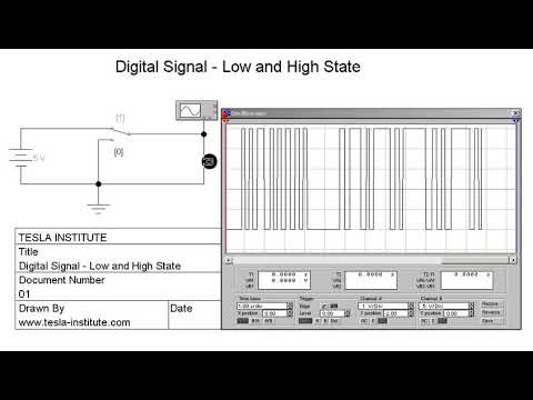
Welcome to TESLA INSTITUTE Facebook Page
Saturday, 16 July 2016
PLC - Principles of operation

A programmable logic controller, as illustrated beow, consists of two basic sections:
• the central processing unit
• the input/output interface system

Programmable controller block diagram
The central processing unit (CPU) governs all PLC activities. The following three components, shown in below, form the CPU:
• the processor
• the memory system
• the system power supply

Block diagram of major CPU components
The
operation of a programmable logic controller is relatively simple. The
input/output (I/O) system is physically connected to the field devices
that are encountered in the machine or that are used in the control of a
process. These field devices may be discrete or analog input/output
devices, such as limit switches, pressure transducers, push buttons,
motor starters, solenoids, etc. The I/O interfaces provide the
connection between the CPU and the information providers (inputs) and
controllable devices (outputs).
During its operation, the CPU completes three processes: (1) it reads, or accepts, the input data from the field devices via the input interfaces, (2) it executes, or performs, the control program stored in the memory system, and (3) it writes, or updates, the output devices via the output interfaces. This process of sequentially reading the inputs, executing the program in memory, and updating the outputs is known as scanning. Figure below illustrates a graphic representation of a scan.

Illustration of a scan
The
input/output system forms the interface by which field devices are
connected to the controller (see Figure below). The main purpose of the
interface is to condition the various signals received from or sent to
external field devices. Incoming signals from sensors (e.g., push
buttons, limit switches, analog sensors, selector switches, and
thumbwheel switches) are wired to terminals on the input interfaces.
Devices that will be controlled, like motor starters, solenoid valves,
pilot lights, and position valves, are connected to the terminals of the
output interfaces. The system power supply provides all the voltages
required for the proper operation of the various central processing unit
sections.

Input/output interface
Although
not generally considered a part of the controller, the programming
device, usually a personal computer or a manufacturer’s miniprogrammer
unit, is required to enter the control program into memory. The
programming device must be connected to the controller when entering or
monitoring the control program.
PLC Training 02 - PLC History PLC Training 03 - Modular and Compact PLCs PLC Training 03 - Modular and Compact PLCs
Tuesday, 5 July 2016
CAN Transceiver

CAN or Controller Area Network is a bus standard designed to allow microcontrollers and devices to communicate with each other without a host computer. Here is the construction details of a do-it-yourself CAN-Bus transceiver using the Microchip’s MCP2551 High-Speed CAN Transceiver IC. The output pins of this circuit can be configured for use with an OBDII cable or a CAN Analyser.
According to datasheet, MCP2551 is a high-speed CAN, fault-tolerant device that serves as the interface between a CAN protocol controller and the physical bus. The MCP2551 device provides differential transmit and receive capability for the CAN protocol controller, and is fully compatible with the ISO-11898 standard, including 24V requirements. It will operate at speeds of up to 1 Mb/s. Typically, each node in a CAN system must have a device to convert the digital signals generated by a CAN controller to signals suitable for transmission over the bus cabling (differential output). It also provides a buffer between the CAN controller and the unwanted high-voltage spikes that can be generated on the CAN bus by external sources.

In the transceiver circuit diagram, connector J1 have 4 connections (VDD/TXD/RXD/GND) and connector J2 have 3 connections (CAN_H/CAN_L/GND) respectively. The jumper JP1, when closed, placed the 120-Ohm terminating resistor across the CAN-High & CAN-Low lines. As stated earlier, you can configure these CAN outputs to use with an OBDII cable or CAN Analyser pinout. The whole circuit can be assembled on a small piece of veroboard. It is better to extend the CAN output connections to a standard DB-9 male-connector (for better flexibility) as per the optional wiring guide shown after the schematic circuit diagram.

For interfacing with your 5V microcontroller, you can directly connect TXD & RXD pins of J1 to your microcontroller’s relevant I/O pins, and CAN_H & CAN_L pins of J2 to the outside device, for example to the OBDII cable, CAN Analyzer, etc.

If your microcontroller is a 3.3V type, a logic level converter should be used to lower the logic levels to 3.3V logic. Note that, an “OBDII to DB9 Cable” allows you to access the pins on your car’s OBDII connector. The cable has an OBDII connector on one end and a DB9 female serial connector on the other. This cable is not meant to be plugged directly into a computer’s serial port. It is meant to plug into some sort of hardware interface, like our transceiver. Here is the basic pinout of the OBDII cable (OBDII → DB9 Female):

CAN & OBDII?
OBD (onboard diagnostics) defines the modern fuel managed vehicles electronic interface system. OBDII is a set of specifications for monitoring and reporting on engine performance in modern automobiles. The OBDII specification provides for a standartized hardware interface the female 16-pin (2×8) J1962 connector, located on the driver’s side of the passenger compartment near the center console.
The CAN bus is simply a pair of wires, often twisted around each other, running around the vehicle and terminated at either end of the two-wire network with resistors of 120 – Ohms. The only components connected to the CAN bus are the electronic control units (nodes). Other components, such as sensors, motors, light bulbs, switches, etc. are wired only to the electronic control units. A vehicle which uses CAN bus for onboard diagnostics can only respond to an OBDII request from a tester which uses CAN. OBDII provides access to numerous data from the Engine Control Unit (ECU) and offers a valuable source of information when troubleshooting problems inside a vehicle. Two wires of CAN bus, CAN_H and CAN_L, will have the same voltage when idle (about 2.5V), or a voltage difference of 2V when a signal is placed on the CAN bus. When a signal is placed on the CAN bus the CAN_H line is at a higher voltage than the CAN_L line. Each electronic control unit have its own CAN identity code, like an address. If an electronic control unit is to communicate to another it will need to know the CAN identity code of the recipient.


